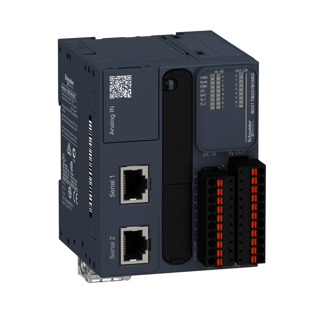
logic controller, Modicon M221, 16 IO, relay, spring
This product is part of the Modicon M221 range, an offer of programmable logic controllers for hardwired architectures. This logic controller provides 8 discrete inputs and 8 relay spring outputs with 10bit input resolution, normally opened relay output. It is a Modicon logic controller with a rated supply voltage of 24V DC, an output voltage of 5V to 125V DC, 5V to 250V AC and an output current of 2A with sink or source input logic. This product requires minimal installation and offers tremendous versatility. Integrated connections are USB port with mini B USB 2.0 connector, non isolated serial link serial 1 with RJ45 connector and RS485 interface and non isolated serial link serial 2 with RJ45 connector and RS232/RS485 interface. It is a Modicon M221 controller with a network frequency of 50/60Hz, 256KB for internal variables RAM, user application and data RAM, a built-in flash memory of 256KB and a SD card memory capacity of 2GB. It is an IP20 rated product. Its dimensions are 70mm (Width) x 70mm (Depth) x 90mm (Height). It weighs 0.264kg. This product is certified by CE, IACS E10, RCM, ABS, LR, DNV-GL, CSA, EAC and CULus. It meets EN/IEC 60664-1, EN/IEC 61131-2 and EN/IEC 61010-2-201 standards. It supports DIN rail mount. Achieve benchmark performance while increasing profitability with the Modicon M221 through intuitive machine programming with SoMachine Basic, ready-to-use applications and function blocks
Brand: Schneider Electric
Add to Quote CatalogueSpecifications
| Product Certifications |
|
|---|---|
| Resistance To Conducted Disturbances |
|
| Resistance To Electromagnetic Fields |
|
| Standards |
|
| Immunity To Microbreaks | 10 ms |
| Storage Altitude | 0-3000 m |
| Pollution Degree | <= 2 |
| Ambient Air Temperature For Operation |
|
| Shock Resistance | 98 m/s² 11 ms |
| Resistance To Magnetic Fields | 30 A/m 50/60 Hz IEC 61000-4-8 |
| Vibration Resistance |
|
| Ambient Air Temperature For Storage | -25-70 °C |
| Environmental Characteristic | ordinary and hazardous location |
| Relative Humidity |
|
| Ip Degree Of Protection | IP20 with protective cover in place |
| Resistance To Electrostatic Discharge |
|
| Surge Withstand |
|
| Resistance To Fast Transients |
|
| Operating Altitude | 0...6561.68 ft (0...2000 m) |
| Electromagnetic Emission |
|
| Discrete Input Logic | sink or source (positive/negative) |
| Data Backed Up | 256 kB built-in flash memory backup of application and data |
| Exct Time For Event Task | 60 µs response time |
| Input Impedance |
|
| Electrical Connection |
|
| Maximum Cable Distance Between Devices |
|
| Height | 90 mm |
| Discrete Input Voltage | 24 V |
| Maximum Power Consumption In W |
|
| Inrush Current | 35 A |
| Discrete Input Voltage Type | DC |
| Communication Service |
|
| Maximum Current Per Output Common | 7 A |
| Transmission Rate |
|
| Clock Drift | <= 30 s/month 25-25 °C |
| Battery Type | BR2032 or CR2032X lithium non-rechargeable |
| Communication Port Protocol |
|
| Protection Type | without protection 5 A |
| Marking | CE |
| Backup Time | 1 year 25 °C by interruption of power supply) |
| Discrete I/O Number | 16 |
| Reset Time | 1 s |
| Regulation Loop | adjustable PID regulator up to 14 simultaneous loops |
| Maximum Number Of I/O Expansion Module |
|
| Power Supply Output Current |
|
| Net Weight | 0.264 kg |
| Application Structure |
|
| Voltage State 0 Guaranteed | <= 5 V input |
| Configurable Filtering Time |
|
| Output Voltage Limits |
|
| Maximum Size Of Object Areas |
|
| Memory Capacity |
|
| Conversion Time | 1 ms per channel + 1 controller cycle time analog input |
| Voltage State 1 Guaranteed | >= 15 V input |
| Control Signal Type |
|
| Supply Voltage Limits | 20.4-28.8 V |
| Integrated Connection Type |
|
| Execution Time Per Instruction | 0.2 µs Boolean |
| Mechanical Durability | 20000000 cycles relay output |
| Electrical Durability |
|
| Absolute Accuracy Error | +/- 1 % of full scale analog input |
| Mounting Support |
|
| Local Signalling |
|
| Response Time |
|
| Discrete Input Current |
|
| Execution Time For 1 Kinstruction |
|
| Analogue Input Resolution | 10 bits |
| Realtime Clock | with |
| Lsb Value | 10 mV |
| Width | 70 mm |
| Depth | 70 mm |
| Minimum Load | 1 mA 5 V DC relay output |
| Data Storage Equipment | 2 GB SD card optional) |
| Insulation |
|
| Supply | serial 1)serial link supply 5 V, <200 mA |
| Counting Input Number | 4 fast input (HSC mode) 100 kHz 32 bits |
| Permitted Overload On Inputs |
|
| Switching Frequency | 20 switching operations/minute with maximum load |
| Rohs Exemption Information | Yes |
| Mercury Free | Yes |
| Environmental Disclosure | ENVPEP1403012EN |
| Sustainable Offer Status | Green Premium product |
| Pvc Free | Yes |
| California Proposition 65 | WARNING: This product can expose you to chemicals including: Lead and lead compounds, which is known to the State of California to cause cancer and birth defects or other reproductive harm. For more information go to www.P65Warnings.ca.gov |
| Weee | The product must be disposed on European Union markets following specific waste collection and never end up in rubbish bins. |
| China Rohs Regulation | X |
| Circularity Profile | ENVEOLI1403012EN |
| Eu Rohs Directive | Pro-active compliance (Product out of EU RoHS legal scope) |
| Country of Origin | China |
| Width | 70 mm |
| Height | 90 mm |
| Weight | 0.264 kg |
| Discrete Output Type | relay normally open |
| Range Of Product | Modicon M221 |
| Discrete Output Number | 8 relay |
| Product Or Component Type | logic controller |
| Discrete Output Current | 2 A |
| Discrete Output Voltage |
|
| Analogue Input Number | 2 0...10 V |
| [Us] Rated Supply Voltage | 24 V DC |
| Discrete Input Number | 8 , discrete input IEC 61131-2 Type 1 |
Documents
- Spec Sheet
- Discover catalog for Modicon M221 Programmable logic controller for hardwired architectures - Catalog+Modicon+M221+Programmable+logic+controller_+February+2023 (pdf)
- Discover Catalog EcoStruxure Machine Expert-Basic Programming software for Modicon M221 logic controller - Catalog+EcoStruxure+Machine+ExpertBasic+Programming+software+for+Modicon+M221+logic+controller (pdf)